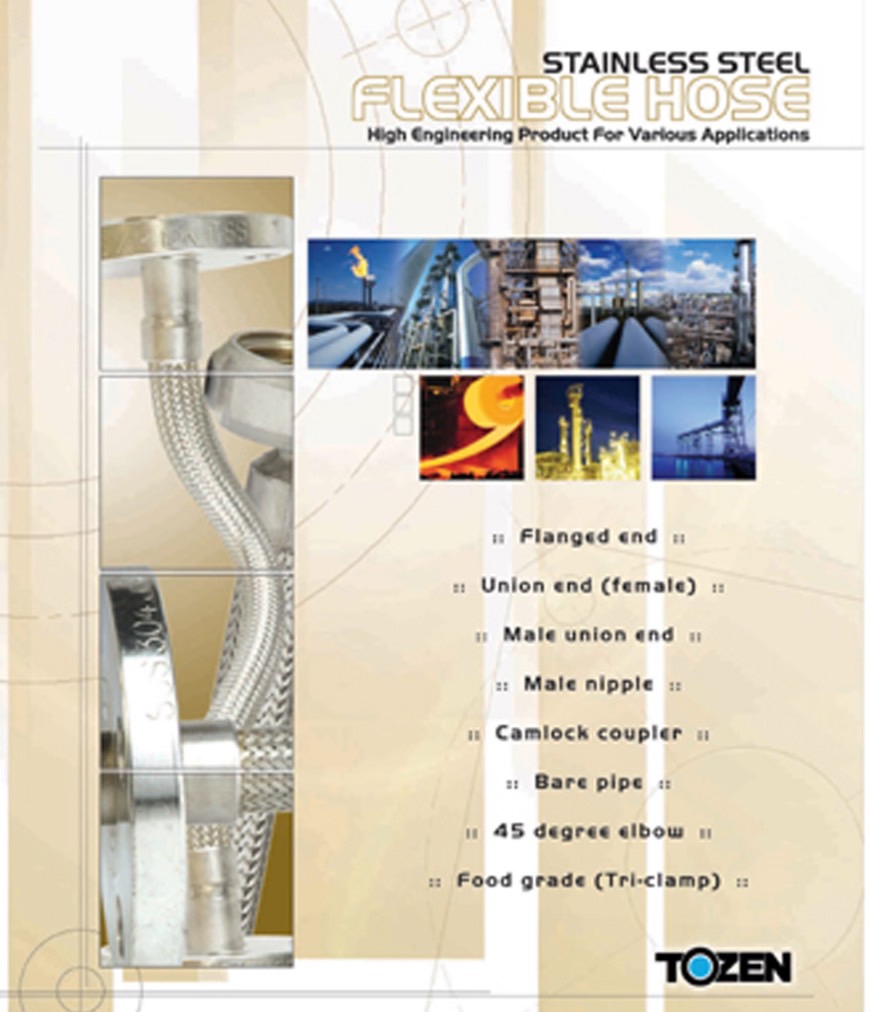
Thermal growth, overloading, metal fatigue, noise, excessive installation time and early maintenance problems can be significantly reduced or avoided with Tozen’s flexible connectors and expansion joints.
Tozen can serve you as a reliable supplier that can fulfill your specific needs. As our factory is located in Thailand, we can offer most standard units with fast delivery for those domestic customers; and if required custom expansion joints or flexible joints will be designed and manufactured to meet your specific applications or special need.
TOZEN braided metal flexible joints are designed to control vibration, reduce noise, relieve stress, prevent system shock and compensate for misalignment and movement. Use of TOZEN braided metal flexible joints for applications such as pumps, compressors, and other mechanical equipment will enhance the overall operation of the system.
Flexible hose by itself, when subjected to high pressure can over-extend past the ability to operate properly it is necessary, therefore, to include an external flexible restraint (i.e. braid) to withstand the specified internal pressure and fastened to the ends of both hose and fittings. This braid sheath is designed to be strong enough to withstand elongation for the full pressure rating of the hose.
Inner hoses and braids can be made from a variety of different metals to meet industry meeds. Common materials used for TOZEN braided metal flexible joints are a 304 stainless steel hose and a 304 stainless steel braid sheath. 316L hoses are available optionally to more corrosive applications. Many kinds of connections (unions, flanges, couplings, etc.) with various materials are available on your request. Please consult us.
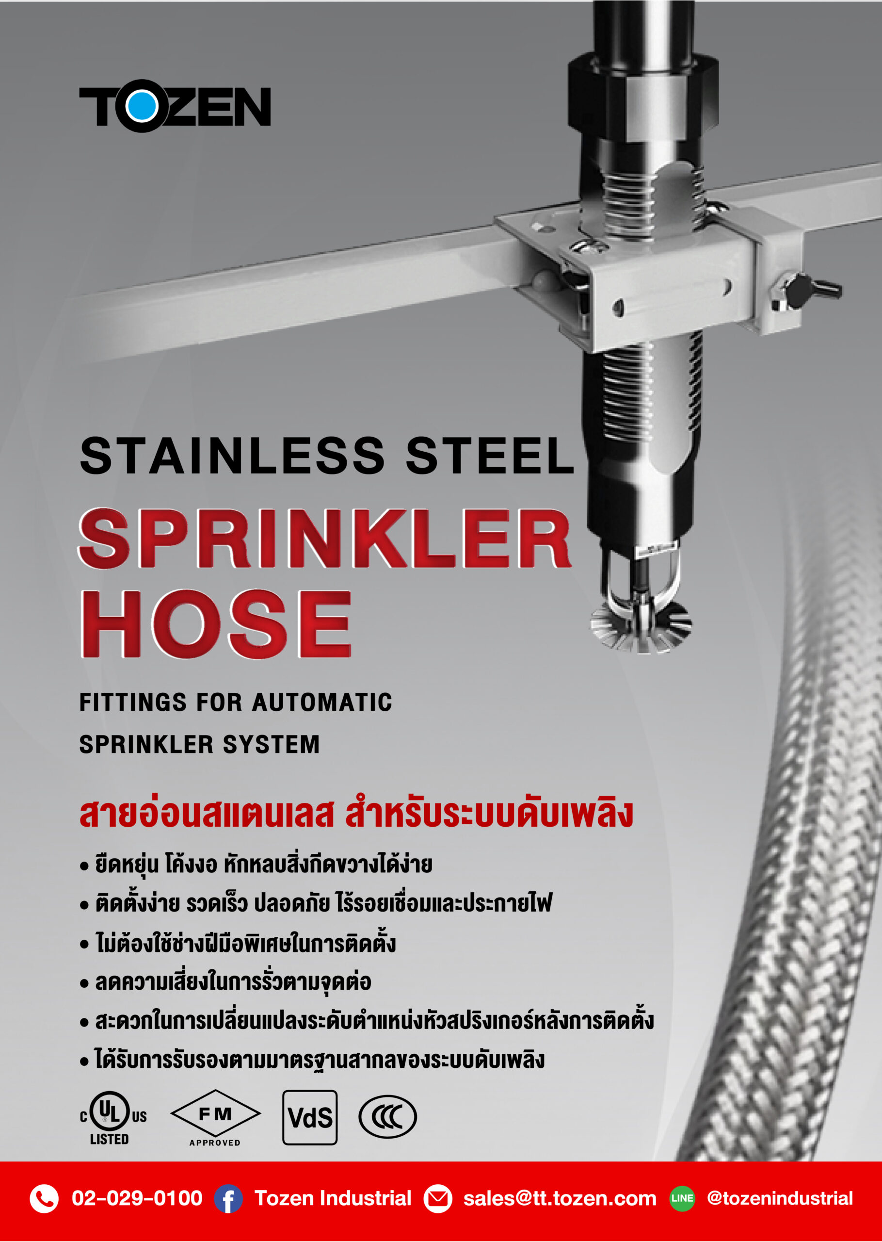
Stainless Steel Sprinkler Hose - Fitting for Automatic Sprinkler System
- Flexibility, Easy to bend to avoid obstacles and quickly installed in tight spaces
- Improved the installation speed
- 100 % safe without leakage
- UL/FM,Vds, 3C Certification
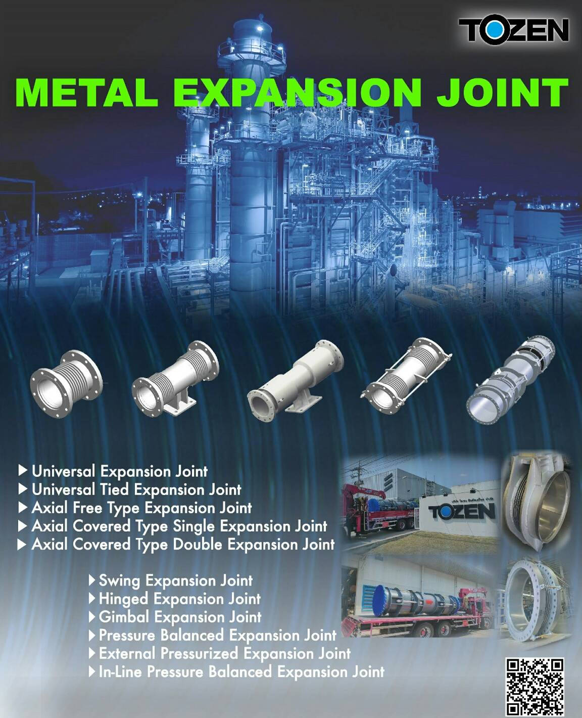
Wherever a pipeline is subjected to temperature change, there is a resultant thermal expansion or contraction. If no provision is made to accommodate this expansion, the Damage to the pipeline and fixings will be considerable. This problem can be simply and quickly remedied by the use of Tozen stainless steel expansion joints. Our extensive range includes expansion joints designed to accommodate all types of movements in axial, lateral, and angular directions.
–> See Catalog
Applications :
Tozen expansion joints are used widely in building services industry and other general industrial uses. Tozen expansion joints are designed to accommodate vibration and thermal expansion to reduce transmission of noise on a wide range of systems. These include steam, condense, hot water, and heating and air conditioning systems. Other applications include power generation plant, offshore (gas and oil rigs), problem, Tozen expansion joints can be your best choice to solve it.
SUS 304 stainless steel is the material most commonly used in the manufacture of bellows for Tozen expansion joints. This is a high quality material suitable for most service conditions. However, a choice of other materials-316L, 321-is available for special applications. Hardware attachments such as flanges, weld ends. liners and covers are generally made from materials compatible with the piping or vessel adjacent to the expansion joint.
Several types of expansion joints are available for a specific need-Axial free Type, Tied Universal Type, Hinge Type, and Gimbal Type. Tozen expansion joints are available from 1.1/2″ up to 20″ for a wide range of working pressures. Larger sizes can be manufactured on request. Please consult us for detailed information.
Notes for Shipment and Installation of Expansion Joints
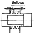 1. Thin-Walled Bellows
Since bellows are made of thin-walled stainless steel plate, careful attention must be taken to avoid damages probably occurring on bellows during shipment and installation.
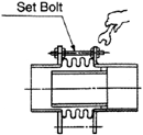 2. Don’t forget to remove ‘Set Bolts’
Do not take off the set bolts if installation of expansion joint is not finished yet. Remember that after installation of the expansion joints are completed and the piping system is ready for operations, do remove the set bolts. The expansion joint shall not function if the set bolts are not taken off.
 3. Flow Direction
Turn and install the expansion joint following the flow direction mark indicated on the joint. Do not install the joint in the wrong flow direction.
4. Installation Direction
Since the movement of an expansion joint with hinges or gimbals under a specific design are limited to certain directions, attention on the installation direction of pins must be taken very carefully to ensure that the joint shall move and function as intended. The installation should follow the drawing of the expansion joints strictly
5. Be careful during site welding
 1) As the wall of the bellows is very thin, do not make arc-strike on the bellows to start arc welding.
 2) Protect the joint from sparks during welding and grinding by covering the joint with sacks, cloths, etc.
Number of Expansion Joints and Installation Length :
>>Number of Expansion Joints Required for a Pipe Section
The displacement length of the thermal elongation and compression can be determined using EQ. (1). From the equation, it shows that the thermal elongation and compression length shall depend on fluid temperature and length of the piping. EQ. (2) is the equation to calculate a number of expansion joints required on the piping to absorb the determined elongation or compression length.
 Calculation of displacement of thermal elongation and compression

Number of Expansion Joints Required

>> Determination of the Installation Length of an Expansion Joint
Expansion joints are generally rated at X movement from free length. To take full advantage of its movement capacity, an expansion joint should be installed so that movement occurs equally about its free position. This shall ensure that the optimum combination of life and movement is achieved. The life of an expansion joint shall be reduced if over-elongated or over-compressed. So it is important to determine a correct installation length of an expansion joint during installation.
The maximum and minimum temperatures of the pipeline need to be known before the anticipated elongation can be calculated (as explained in the preceding topic). Furthermore the installation temperature must also be determined in order to determine the correct installation length of the expansion joint. The following equation (EQ. (3)) shall be used to determine the installation length of an expansion joint under a specific condition of maximum axial displacement and maximum face-to-face length of the expansion joint, maximum and minimum temperatures of the pipeline, ambient installation temperature, and linear elongation coefficient of the pipeline.
Ls = Le – Xa [(t2 – t1)/(T – t1)] …………EQ. (3)
ℓ : Length of Pipeline Section (between 2 anchors) (mm)
Ls : Installation Length (mm)
Le : Maximum face-to-face length (fully-extended length) (mm)
Xa : Maximum axial displacement of the expansion joint (2X) (mm)
T : Maximum working temperature of the pipeline (degree C)
t1 : Minimum working temperature of the pipeline (degree C)
t2 : Ambient installation temperature (degree C)
ɑ : Linear elongation coefficient of the pipeline (/degree C)
Facolex is a flexible hose, which is primarily used as a connector to fan coil units and sanitary equipment. With our engineered structural design of Facolex, water leakage is under less chance to occur. Construction consists of an extruded rubber tube with an overlay of stainless steel braid resulting in a flexible and durable hose assembly, which makes installation much easier. Excellent aging resistance, heat and pressure reliability gives this hose a long usage life.
Facolex are available from sizes 15 mm – 25 mm (1/2″ – 1″) with threaded end connections. Maximum operating pressures are 20 bars and 16 bars for 1/2″ and3/4″ sizes respectively. 10 bars is the maximum operating pressure for 1″. Contact us for detailed information and catalog
Installation Instruction :
– The joint elongates a little by pressurizing.
– Make the joints loose to install.
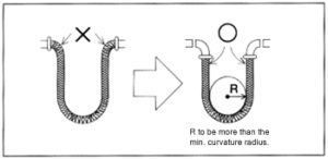
– The installation in excessive bending or unusual curving may shorten the useful life of the joints.
– Use an elbow for the small bending portion and install the joints to work in more than the min. curvature radius.
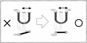
– Pay attention the joints not to be twisted when tightening up the union nut during. installation. In case of continuous displacement, make piping to have the direction of displacement the same level with bending of the joints and avoid distortion. (Distortion makes the metal fittings loose and damages the joints in early stage. Use 2 pcs. of wrench not to make distortion securely.)
There are 2 kinds of the metal end fittings, nipple and adaptor. Install the joints as per the following procedures.
1. Nipple (Male thread)
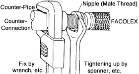
Wind the sealing tape (or other sealing materials) the nipple is tightened up by hand up to certain pitch as much as possible checking no damage of the counter pipe, then set a wrench to the counter pipe to tighten up the nipple. In case of removing or putting back the nipple after completion of tightening up once, clean up foreign obstacles of the thread and replace the sealing tape (or other sealing materials) to tighten up.
2. Adaptor (Female thread)
– Check no damage on the counter connection thread and check the counter connection to be flat face for gasket.
– Put a gasket into the adaptor and tighten up by hand up to certain pitch as much as possible.
– Set a wrench to the counter connection (nipple, etc.) not hose be twisted and tighten up the adaptor by the wrench, etc.
– In case of removing or putting back the adaptor after completion of tightening up once, replace the gasket to new one and tighten up again.
– Do not use other gaskets except the attached ones. Some improper conditions like leakage, etc. may happen due to use of gaskets other than the attached ones.
– If you found out the shortage of gaskets when installation, please consult us at once.
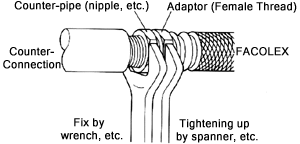

Standard Tightening Torque for Adaptor
| Nominal Dia. | Standard Tightening Torque [N.cm] (kgf.cm) |
| 15A | 2900 (300) |
| 20A | 5900 (600) |
| 25A | 9800 (1000) |
| 32A | 14700 (1500) |
| 40A | 19600 (2000) |
| 50A | 29400 (3000) |
The body of the joints is made of rubber. The joints cannot be used near the heat source where the high temp. is generated. When welding or cutting the pipes nearby after installation, protect the joints with a cover like our SPARK GUARD from sparks. In case of possibility of heat transmission when welding or cutting and damage by sparks when welding, take the joints off from the pipe first surely and then start working.

STAINLESS STEEL EXPANSION JOINT MOVEMENT
- Model: SJT1100
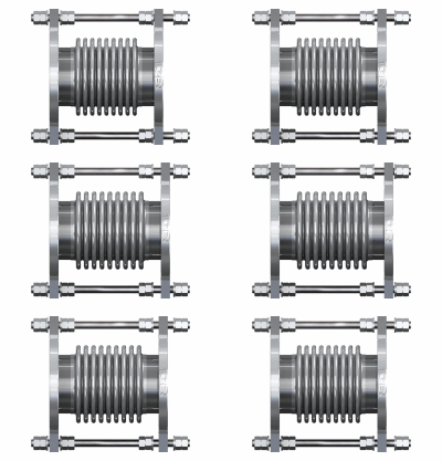
Axial Movement
- Model: SJT1200
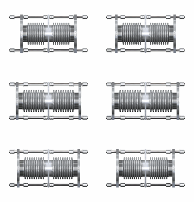
Axial Movement

